2017年12月6日星期三

Mixtile GENA: Inexpensive Hackable Smartwatch

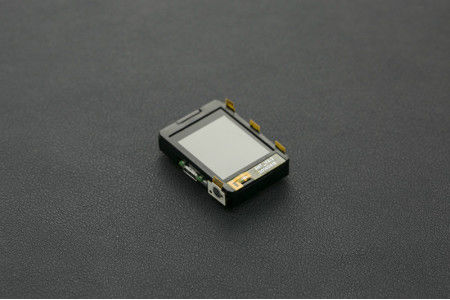
If you've ever wanted to have your own hackable smartwatch, the Mixtile GENA -A Wearable Electronic Development Kit is your $35 answer. This little device packs in a BLE modem, a transflective LCD display, a vibration motor, motion sensors, and a LiPoly battery big enough to power the whole package for four days straight. In this tutorial I'll go through the process of how you can get started with your device and the various features it offers.Step 1: Purchasing Your GENA

DFRobot is a great place to buy the Gena. You can pick one up from their storefor less than $35.Unfortunately, the GENA only supports iOS devices. If you have an iPhone or an iPad that supports Bluetooth low energy the GENA will be compatible with your device. If you're interested in utilizing the GENA for development purposes that don't require an active connection to a smart device then the GENA should work fine. You don't need an iOS device to setup the GENA, but a device is required to automatically set the time, receive notifications, or utilize other smart features such as the shutter.Step 2: Initial Setup

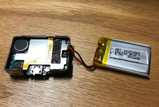
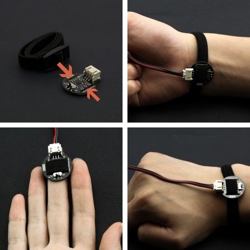
One thing I highly recommend before playing around with your new smart device is to better affix the battery. My GENA arrived with the battery separated from the rest of the case. To ensure that it stays on properly get some double-sided tape or some super glue and re-attach the battery to the rest of the device.Similarly, the adhesive holding the buttons to the plastic didn't do a very good job. I had to use more super glue to re-attach the flex-PCB where the buttons are mounted.Step 3: Changing the Language

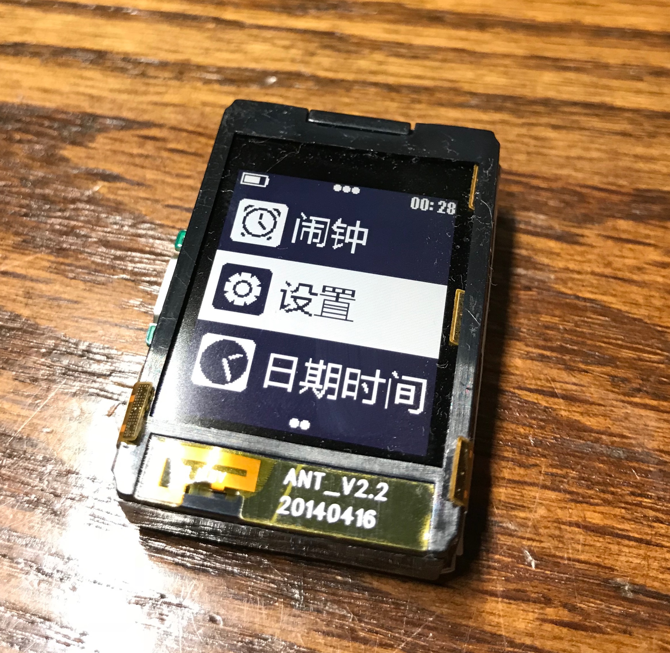
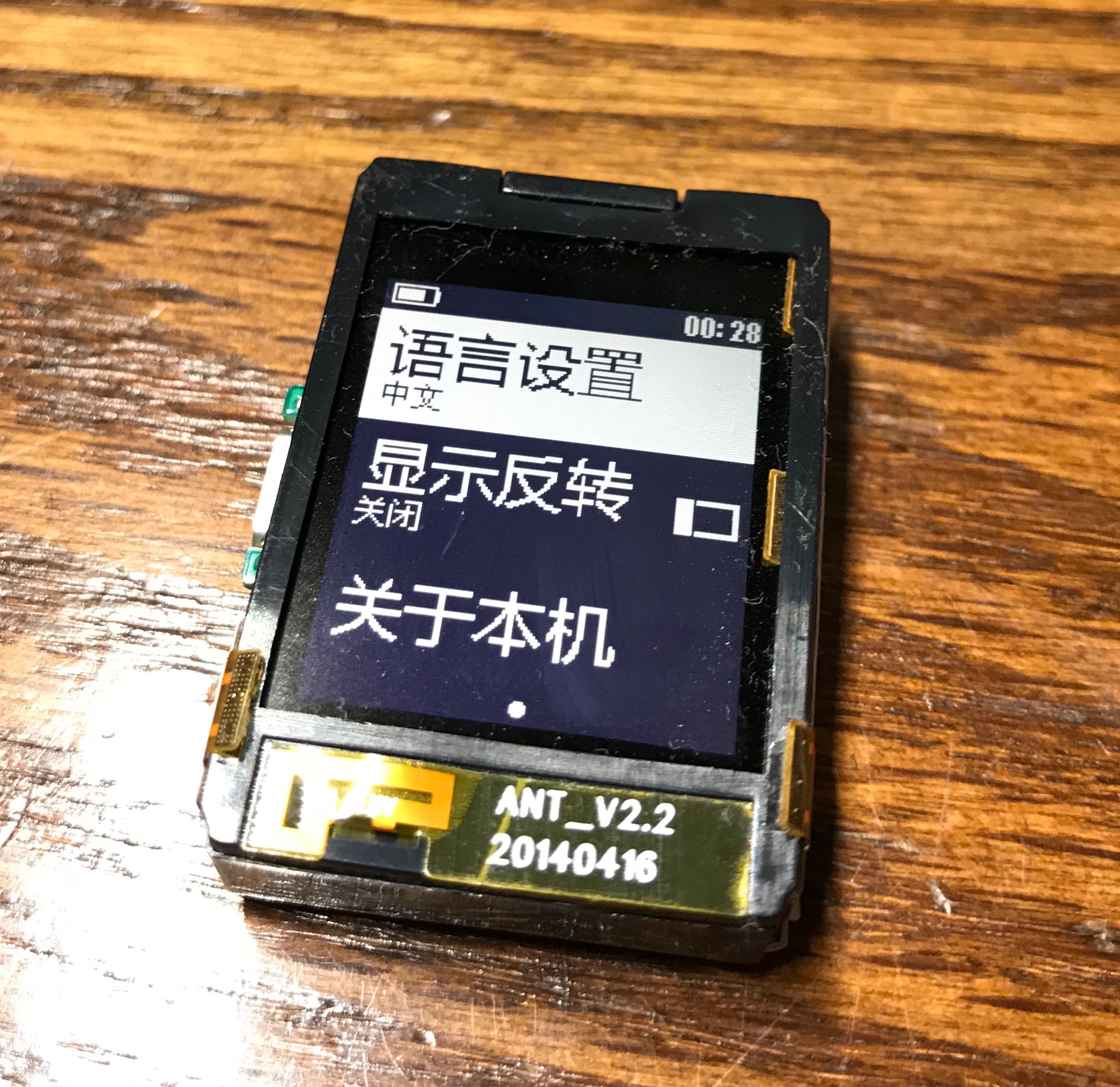
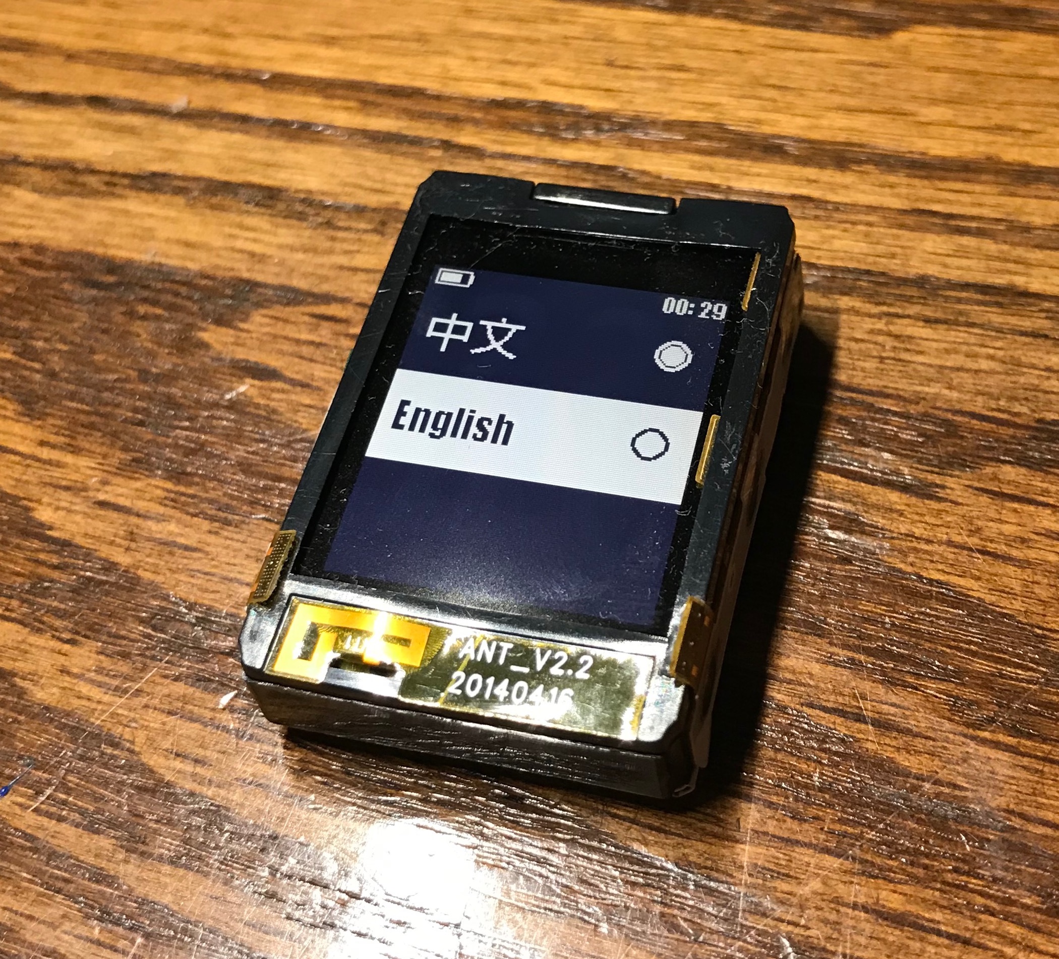
It is a bit difficult to change the GENA's language to English, as all the menu options are in Chinese by default! I managed to blunder my way through it, though. To change the language to English follow the instructions below:From the watch face press the center button on the right side of the devicePress the down button eight timesPress the center button againPress the center button one more timeScroll down to English using the down buttonSelect EnglishAnd there you have it! If the text-based instructions are unclear I have also included photos above.

Step 4: Pairing With an IOS Device

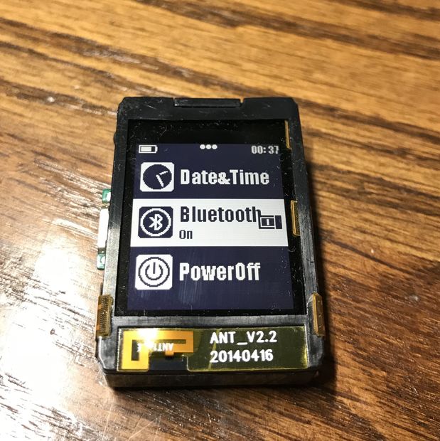
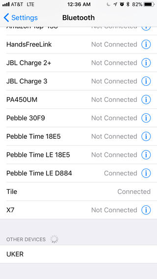
As mentioned previously, pairing and data transmission is only compatible with iOS-based systems. That being said, notification and information transfer with iOS devices "just works" without the need for another app. After you pair your GENA the date, time, and all notifications will go to the GENA automatically.Here's how you can go about pairing with your iPhone or iPad:From the watchface press the center button and scroll down to BluetoothIf it isn't already enabled press the center button to do soNow you can go into Bluetooth settings on your iOS device and select your GENA. Mine was called "UKER" but yours could be different. Select it from the "Other Devices" list and the two should pair.

Step 5: Built-In Apps

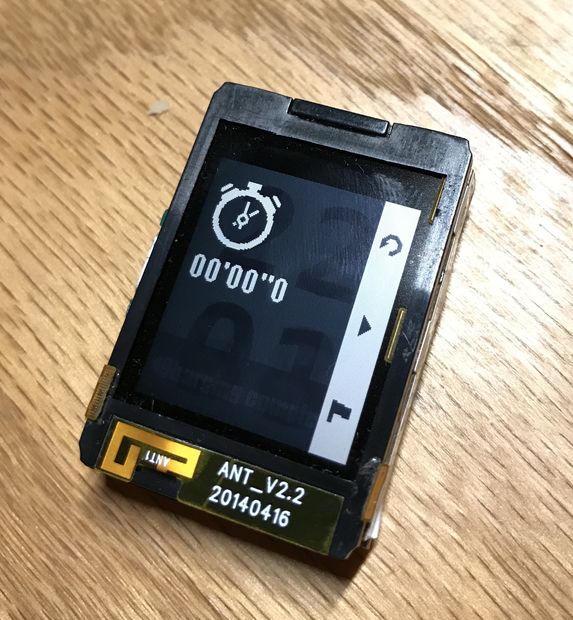
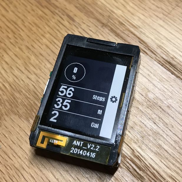
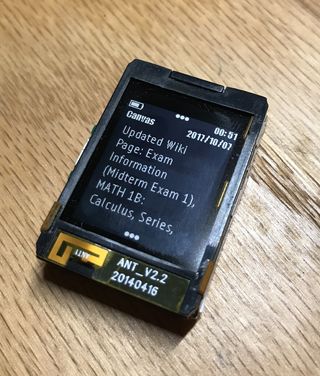
Your GENA comes with a variety of baked-in apps. Some of these work out of the box, while some require an active Bluetooth connection. I'll describe all the available feature below:Watchfaces:The GENA comes with a few built-in watchfaces. My go-to is one that literally just displays the time in large type, but there's also an analog option and a few others. They are somewhat aesthetically pleasing but have limited customization options.Notifications:Notification delivery is consistent and vibrations are noticeable without being intrusive.Sport:Your GENA has an integrated accelerometer/gyroscope module so it has the ability to count steps. I took both my GENA and my Pebble Time Round on a 1500-step walk and both were within 100 steps of each other. Clearly the accuracy of the GENA is comparable to more established devices. As with any step-based tracking device distance measurements were way off.Music Control:When paired to an iPhone or iPad you can control the music of that device from your GENA. This works reliably without hiccups.Camera:The remote shutter function also works just fine. It simply sends a volume up button press event to the paired device which triggers the shutter.Find Phone:This one is still an enigma to me. Apparently it needs an app to be installed on the phone in order for it to work, but that app doesn't appear to be on the App Store.Stopwatch:A basic stopwatch. It gives you time to the accuracy of a tenth of a second and has rudimentary split functionality.Timer:Just a simple timer with no customization options other than the time. It works fine.Alarm:I tried this one out on a much-needed nap. I strapped my GENA to my wrist, set the alarm for a time two hours in the future, and fell asleep. The watch woke me up with powerful vibrations right on time. If you're afraid that you won't be able to feel the alarm going off you can rest easy. It's very powerful and noticeable.

Step 6: Wrapping Up

In conclusion, the Mixtile GENA is a great introductory device for smartwatch enthusiasts. It may not have the largest featureset or the greatest looks but it is a fun little device to play around with.It's apparently possible to develop applications for this device, but I haven't been able to find any documentation online that explains the procedure for doing this. I contacted Mixtile engineers and haven't yet heard back. If/when I do I will update this tutorial with more information on how to make new apps for the GENA.

2017年12月5日星期二

How to make a Heart Rate Monitor

In this project we are going to make a Heart Beat Detection and Monitoring System using Arduino that will detect the heart beat using the Pulse Sensor and will show the readings in BPM (Beats Per Minute). It will also send the readings to ThingSpeak server using the Wi-Fi Bee module ESP8266, so that Heart Beats can be monitored from anywhere in the world over the internet. ThingSpeak is a great source for displaying the data online and you can access the data from ThingSpeak at any time and at any place.


Components Required
Hardware:

Arduino UNO Rev3I/O Expansion Shield for ArduinoHeart Rate SensorESP8266 WiFi Bee

Software or online services:
Arduino IDE
Thingspeak API
Setting up the ThingSpeak

ThingSpeak provides very good tool for IoT based projects. By using ThingSpeak site, we can monitor our data and control our system over the Internet, using the Channels and webpages provided by ThingSpeak. ThingSpeak ‘Collects’ the data from the sensors, ‘Analyze and Visualize’ the data and ‘Acts’ by triggering a reaction. We have previously used ThingSpeak in Weather station project using Raspberry Pi and using Arduino, check them to learn more about ThingSpeak. Here we are briefly explaining to use ThingSpeak for this Beat Detection and Monitoring System. The ThingSpeak service is operated by MathWorks.

First of all, user needs to Create a Account on ThingSpeak.com, then Sign In and click on Get Started.

After creating an account, go to channels and create a new channel. Now write the name of the Channel and name of the Fields. Also tick the check box for ‘Make Public’ option below in the form and finally Save the Channel. Now your new channel has been created.

After this go to API keys and copy your Write API key. You will need this in the code. Check the Full Code at the end.


Circuit and Explanation

ESP8266 WiFi Bee

Wifi Bee-ESP8266 is a Serial-to-WIFI module using XBEE design in a compact size, compatible with XBEE slot, applicable to a variety of 3.3V single-chip system. It can be used for Arduino, wireless data transfer, remote control. On-board switch can be used to easily select the Startup module or Upgrade firmware. ESP8266 arduino module has a powerful on-chip processing and storage capacity, built-in 32-bit processor, built-in Lwip protocol stack. Support AP+STA mode co-exist.

Heart Rate Sensor Module

The DFRobot heart rate sensor is a thumb-sized heart rate monitor designed for Arduino microcontrollers.

This heart rate monitor sensor is a pulse sensor which is developed based on PPG techniques. This is a simple and low-cost optical technique that can be used to detect blood volume changing in the microvascular bed of tissues. It is relatively easy to detect the pulsatile component of the cardiac cycle according to this theory.

The sensor has two holes that you can use to attach to your belt. You can wrap on your finger, wrist, earlobe or other areas where it has contact with your skin.

I/O Expansion Shield
To connect these components with the Arduino, we need the expansion shield which can connect them with the microcontroller with ease.

Connections

            1. Stack the I/O Expansion Shield on the Arduino UNO.
            1. Take the Heart Rate Sensor Module and put the strap through the holes in the modules so that you can wrap on your finger, wrist, earlobe or other areas where it has contact with your skin.
            1. Connect the Heart Rate Sensor Module to A1 pin on the analog headers on the expansion shield. Mind the colors of headers to the wires, that is, red to red, etc.
            1. In the Wifi Bee slot on the shield, put the ESP8266 WiFi Bee.


            Uploading and testing

                                        1. Wrap the strap around your finger or wrist.
                                        1. Put the switch on the module to 'A' for analog mode.
                                        1. Now, upload the sketch for testing the module for the first time.
                                        1. Open serial plotter and wait for 5 seconds and stay calm.
                                        1. You will see the graph of the heart beats.
                                        1. Try to block the blood flow through using another hand.
                                        1. The graph line will become straight for some time and will come to normal stage as the blood finds way for circulation if all the capillaries aren't blocked properly.


                                        NOTE:

                                        1. This product is NOT a professional medical device and should not be used to diagnose or treat medical conditions.

                                        2. This sensor is designed to work when the user is not moving. If used while moving it will give inaccurate results.

                                        • Now, upload the main code to the Arduino.
                                        • Remember to change the API key, SSID (WiFi name) and PASS (Password) for your project.
                                        • Use the heart rate sensor on your self again.

                                        The ESP8266 will then communicate with the Arduino and will send the data to ThingSpeak. The ESP8266 will connect the network of your router that you will provide in the code and will send the data of the sensor online. This data on the ThingSpeak will be shown in a Graph form showing the past readings too and can be accessed from anywhere over internet.

                                        CODE

                                        int sensorPin = A1;   //for analog input
                                        //remember you put the switch towards 'A' not 'D' for analog input
                                        
                                        void setup()  {
                                          Serial.begin(115200);
                                          //default is 9600, change after opening the serial plotter
                                         }
                                        
                                        void loop()  {
                                          int heartValue = analogRead(heartPin);    //reading the analog value
                                          Serial.println(heartValue);   //printing the value tot the serial plotter
                                          delay(5);
                                          }

                                        2017年12月4日星期一

                                        LED Controlled by 3D Gesture Sensor

                                        Things used in this project

                                        1.Arduino Uno & Genuino UNO2.DFRobot Flexible 8x8 RGB LED Matrix3.DFRobot 3D Gesture Sensor4.Arduino IDE

                                        Configuration

                                        I Tried controlling the display of flexible LED matrix with 3D gesture sensor.


                                        Display the eye on the LED matrix and move with the 3D gesture sensor.


                                        Flexible 8x8 RGB LED Matrix

                                        It has a 8x8 full color LED(NeoPixel) and soft by flexible board. The Arduino library for Neopixels is located in following.

                                        Please refer below for product details.

                                        https://www.dfrobot.com/wiki/index.php/Gravity:_Flexible_8x8_RGB_LED_Matrix_SKU:_DFR0461

                                        3D Gesture Sensor

                                        Five electrodes are arranged in the up, down, left, right, and middle. Gesture is sensored by changes in electrostatic capacitance of electrodes due to hand approach.


                                        The Arduino Library for the 3D Gesture Sensor is located in the following. 

                                        https://github.com/DFRobot/DFRobot_Gesture


                                        This gesture sensor detects clockwise/counterclockwise rotation and movement directions(up, down, left, right) using program example"3D Gesture Test"


                                        Arduino Programing

                                        Display the eyeball on the LED matrix, move the eyes right and left with the left and right sensing of the gesture sensor. open and close the eyelids by vertical sensing. The pupil faces the front in clockwise or counterclockwise sensing. 


                                        LED Array:


                                        Code:
                                        #include  
                                        #include  
                                        #include  
                                        int sensePin= A1; 
                                        unsigned char cmd; 
                                        DFRobot_Gesture myGesture; 
                                        #define DIN A0 
                                        Adafruit_NeoPixel led = Adafruit_NeoPixel(64, DIN, NEO_GRB + NEO_KHZ800); 
                                        int LR = 5; 
                                        int eyelid = 0; 
                                        int whiteNum = 52; 
                                        int blackNum = 20; 
                                        int pupilNum = 12; 
                                        //white eye 
                                        int whiteLED[52] = { 2,  3,  4,  5,  9, 10, 11, 12, 13, 14, 16, 17, 18, 19, 20, 21, 22, 23, 24, 25, 26, 27, 28, 29, 30, 31,   
                                                                 32, 33, 34, 35, 36, 37, 38, 39, 40, 41, 42, 43, 44, 45, 46, 47, 49, 50, 51, 52, 53, 54, 58, 59, 60, 61}; 
                                        //black eye 
                                        int blackLED[11][20] = {{50, 51, 52, 53, 58, 61, 64, 64, 64, 64, 64, 64, 64, 64, 64, 64, 64, 64, 64, 64}, 
                                                                     {42, 43, 44, 45, 49, 50, 53, 54, 64, 64, 64, 64, 64, 64, 64, 64, 64, 64, 64, 64}, 
                                                                     {34, 35, 36, 37, 41, 42, 45, 46, 49, 54, 64, 64, 64, 64, 64, 64, 64, 64, 64, 64}, 
                                                                     {26, 27, 28, 29, 33, 34, 37, 38, 41, 46, 54, 49, 58, 61, 61, 64, 64, 64, 64, 64}, 
                                                                     {18, 19, 20, 21, 25, 26, 29, 30, 33, 38, 41, 46, 49, 50, 53, 54, 58, 59, 60, 61}, 
                                                                     {10, 11, 12, 13, 17, 18, 21, 22, 25, 30, 33, 38, 41, 42, 45, 46, 50, 51, 52, 53}, 
                                                                     { 2,  3,  4,  5,  9, 10, 13, 14, 17, 22, 25, 30, 33, 34, 37, 38, 42, 43, 44, 45}, 
                                                                     { 2,  5,  9, 14, 17, 22, 25, 26, 29, 30, 34, 35, 36, 37, 64, 64, 64, 64, 64, 64}, 
                                                                     { 9, 14, 17, 18, 21, 22, 26, 27, 28, 29, 64, 64, 64, 64, 64, 64, 64, 64, 64, 64}, 
                                                                     { 9, 10, 13, 14, 18, 19, 20, 21, 64, 64, 64, 64, 64, 64, 64, 64, 64, 64, 64, 64}, 
                                                                     { 2,  5, 10, 11, 12, 13, 64, 64, 64, 64, 64, 64, 64, 64, 64, 64, 64, 64, 64, 64}}; 
                                        //pupil 
                                        int pupilLED[11][12] = {{59, 60, 64, 64, 64, 64, 64, 64, 64, 64, 64, 64}, 
                                                                     {51, 52, 58, 59, 60, 61, 64, 64, 64, 64, 64, 64}, 
                                                                     {43, 44, 50, 51, 52, 53, 58, 59, 60, 61, 64, 64}, 
                                                                     {35, 36, 42, 43, 44, 45, 50, 51, 52, 53, 59, 60}, 
                                                                     {27, 28, 34, 35, 36, 37, 42, 43, 44, 45, 51, 52}, 
                                                                     {19, 20, 26, 27, 28, 29, 34, 35, 36, 37, 43, 44}, 
                                                                     {11, 12, 18, 19, 20, 21, 26, 27, 28, 29, 35, 36}, 
                                                                     { 3,  4, 10, 11, 12, 13, 18, 19, 20, 21, 27, 28}, 
                                                                     { 2,  3,  4,  5, 10, 11, 12, 13, 19, 20, 64, 64}, 
                                                                     { 2,  3,  4,  5, 11, 12, 64, 64, 64, 64, 64, 64}, 
                                                                     { 3,  4, 64, 64, 64, 64, 64, 64, 64, 64, 64, 64}}; 
                                        //eyelid 
                                        int eyelidNum[8] = {0,4,8,14,20,28,36,44}; 
                                        int eyelidLED[56] = {23, 24, 39, 40, 22, 25, 38, 41,  9, 21, 26, 37, 42, 54, 10, 20, 27, 36, 43, 53,  5, 11,  
                                                            19, 28, 35, 44, 52, 58,  4, 12, 18, 29, 34, 45, 51, 59,  3, 13, 17, 30, 33, 46, 50, 60}; 
                                        void setup(){ 
                                         Wire.begin();        // join i2c bus (address optional for master) 
                                         Serial.begin(115200);  // start serial for output 
                                         pinMode(sensePin, INPUT); 
                                         led.begin(); 
                                         led.setBrightness(100); //LED brightness 0-255  
                                         blink(LR, eyelid); 
                                        } 
                                        void loop(){ 
                                         if(digitalRead(sensePin)==0){   
                                           myGesture.I2C1_MasterRead(md.buf,26,0x42); //The address is:0x42 
                                           cmd = myGesture.mgcProcMsg();     //process the message 
                                           if(cmd != GI_NOGESTURE ){ 
                                             switch(cmd){ 
                                               case GI_FLICK_R: 
                                                 Serial.println("RIGHT"); 
                                                 //Move the eye right 
                                                 for(int i = LR; i <= 10; i++){ 
                                                   blink(i, eyelid); 
                                                   delay(100); 
                                                 } 
                                                 LR = 10; 
                                                 break; 
                                               case GI_FLICK_L: 
                                                 Serial.println("LEFT"); 
                                                 //Move the eye left 
                                                 for(int i = LR; i >= 0; i--){ 
                                                   blink(i, eyelid); 
                                                   delay(100); 
                                                 } 
                                                 LR = 0; 
                                                 break; 
                                               case GI_FLICK_D: 
                                                 Serial.println("DOWN"); 
                                                 //Eyelid close 
                                                 for(int i = eyelid; eyelid <= 8; eyelid++){ 
                                                   blink(LR, eyelid); 
                                                   delay(100); 
                                                 } 
                                                 eyelid = 8; 
                                                 break; 
                                               case GI_FLICK_U: 
                                                 Serial.println("UP"); 
                                                 //Eyelid open 
                                                 for(int i = eyelid; eyelid >= 0; eyelid--){ 
                                                   blink(LR, eyelid); 
                                                   delay(100); 
                                                 } 
                                                 eyelid = 0; 
                                                 break; 
                                               case GI_AIRWHEEL_CW://Clockwise in circles 
                                                 Serial.println("CW"); 
                                                 //Return eye to the front 
                                                 Return(); 
                                                 break; 
                                               case GI_AIRWHEEL_CCW://Counterclockwise circles 
                                                 Serial.println("CCW"); 
                                                 //Return eye to the front 
                                                 Return(); 
                                                 break; 
                                               default: break; 
                                               } 
                                             } 
                                           } 
                                        } 
                                        void blink( int LR, int eyelid) { 
                                         if (eyelid != 8){ 
                                           //white eye 
                                           for(uint16_t i=0; i= 5; i--){ 
                                             blink(i, eyelid); 
                                             delay(100); 
                                           } 
                                         } 
                                         LR = 5; 
                                        }

                                        2017年12月3日星期日

                                        Raspberry Pi tutorial– Using the Raspberry Pi Camera

                                        Specifications:

                                        Lens: ¼ - 5MPAperture: 2.9Focal length: 3.29Field of view angle: 72.4 degrees 

                                        Hardware Setup:1. CSI connector; 90 degrees vertical connector which is next to the HDMI port. When connecting, make sure one side of the contact faces the HDMI interface. 
                                        2. Do not forget to tear off the protective film off of the camera lens!3. Also, since the Raspberry Pi is a bare silicon board, take care to not get any electro-static damage!Raspberry Pi Set up – Enabling the Camera1. Open the Command Prompt line
                                        2.
                                        3.
                                        4.
                                        5.
                                        6.
                                        Software Setup:
                                        1. RPi firmware and raspi-config have been updated for the camera, please execute apt-get update; Its available online.
                                        2. Select the camera in raspi-config, start the camera driver in the RPi firmware, and then reboot the board.
                                        Command to Activate the camera:
                                        raspistill -t 20000 -o –

                                        raspistill -t 2000 -o image.jpg < / font>
                                        raspistill-t 2000 -o image.jpg -w 640-h 480
                                        raspistill -t 2000 -o image.jpg -q 5
                                        raspistill -t 2000 -o image.jpg - p 100,100,300,200
                                        raspistill -t 2000 -o image.jpg –n
                                        raspistill -t 2000 -o image.png - e png
                                        raspistill -t 2000 -o image.jpg -x IFD0.Artist = Dreamcolor -x GPS.GPSAltitude = 1235/10
                                        raspistill -t 2000 -o image.jpg -ifx emboss
                                        raspistill -t 2000 -o image.jpg -cfx 128: 128
                                        raspistill -t 2000
                                        raspistill -t 600000 -tl 10000 -o image_num_ % d_today.jpg
                                        raspistill -t 2000 –o
                                        raspistill -t 2000 -o -> my_file.jpg
                                        Camera Tech Specs:
                                        Sensor size: 3.67 x 2.74 mm (1/4 "format 
                                        Pixel Count: 2592 x 1944 
                                        Pixel Size: 1.4 x 1.4 um 
                                        Lens: f = 3.6 mm, f / 2.9 
                                        Angle of View: 54 x 41 degrees 
                                        Field of View: 2.0 x 1.33 m at 2 m 
                                        Full-frame SLR lens equivalent: 35 mm 
                                        Fixed Focus: 1 m to infinity 
                                        Video: 1080p at 30 fps with codec H.264 (AVC) 
                                        Up to 90 fps Video at VGA 
                                        Board size: 25 x 24 mm (not including flex cable)
                                        Because the focal length of the lens is roughly the same as the width of the sensor, it is easy to remember the field of view: at x meters away, you can see about x meters horizontally, assuming 4x3 stills mode. Horizontal field of view in 1080p video mode is 75% of that (75% H x 55% V sensor crop for 1: 1 pixels at 1920x1080). 

                                        The Raspberry Pi Camera Board features a 5MP (2592×1944 pixels) OmniVision 5647 sensor in a fixed focus module. The module attaches to Raspberry Pi, by way of a 15 Pin Ribbon Cable, to the dedicated 15-pin MIPI Camera Serial Interface (CSI), which was designed especially for interfacing to cameras. The CSI bus is capable of extremely high data rates, and it exclusively carries pixel data to the BCM2835 processor. It is fully Compatible with Both the Model A. Model B Raspberry Pi and B+. 

                                        # Take photo and send it to the standard output device for 20s

                                        #two seconds (in milliseconds) delay to take a picture and save it as image in jpg

                                        #Take a custom size photo.
                                        #Reduce the image quality and reduce the file size
                                        #Force the preview window to appear at a position of 100, 100, with a width of 300 and a height of 200 pixels.
                                        #Disable the preview window
                                        #Save the image as a PNG file (lossless compression format, but slower than JPEG). Note that when selecting image encoding, the file extension will be ignored.
                                        #Add some EXIF ​​information to the JPEG file. The command will set the author name tag to Dreamcolor, and the GPS altitude is 123.5 meters.
                                        #Set embossed style image effects
                                        #Set the U and V channels of the YUV image to the specified value (128: 128 is the black and white image)
                                        #Display only two seconds to preview the image without saving the image.
                                        #Get the picture at 10 minutes (10 minutes = 600000 milliseconds), get a copy every 10 seconds, and name it image_number_1_today.jpg, image_number_2_today.jpg and so on…
                                        #Get a photo and send it to a standard output device
                                        #Get a photo and save it as a file

                                        Sensor type: OmniVision OV5647 Color CMOS QSXGA (5-megapixel) 

                                        2017年12月2日星期六

                                        Raspberry Pi 3 Project: A Door Guardian

                                        Have you ever wanted to catch that one person who keeps stealing your Halloween candy? Or what about that annoying roommate who won't leave your fridge alone? By using a Raspberry Pi 3, Pi Camera, and PIR sensor, all of that is now possible. Simply put it in a location you want monitored and get emailed with an attached photo of the perpetrator.


                                        THINGS USED IN THIS PROJECT
                                        DFRobot Raspberry Pi 3 salesDFRobot Raspberry Pi Camera ModulePIR Motion Sensor (generic)


                                        Software apps and online services:

                                        Python IDE of Choice

                                        Setting Up the Pi

                                        DFRobot reached out to me and sent their Raspberry Pi 3 and Raspberry Pi Camera Module. So after I opened up the boxes I got right to work by setting up the SD card. First I went to the Raspberry Pi Downloads page and downloaded the most recent version of Raspbian. I then extracted the file and put it into a convenient directory. You can't just copy/paste a .img file to an SD card, you have to "burn it" onto the card. You can download a burning utility like Etcher.io to easily transfer the OS image. After the .img file was on my SD card I inserted it into the Raspberry Pi and gave it power. After about 50 seconds I unplugged the cord and removed the SD card. Next I put the SD card back into my PC and went to the "boot" directory. I opened up notepad and saved it as a blank file named "ssh" with NO extension. There was also a file I added called "wpa_supplicant.conf" and put this text into it:

                                        network={
                                             ssid=<"SSID">
                                             psk=<"PASSWD">
                                        }

                                        Then I saved and ejected the card and put it back into the Raspberry Pi 3. This should now allow for the usage of SSH and connecting to WiFi.

                                        Getting the Camera Ready
                                        By default, the camera is disabled on the Pi, so you must open the terminal type sudo raspi-config to bring up the menu. Go to "interfacing options" and then enable the camera. Now just select "Finish" and insert the ribbon cable of the camera module into the correct area of the Pi.

                                        Wiring the PIR Sensor
                                        A PIR sensor stands for Passive InfraRed, which basically means it can detect heat, and therefor humans moving in front of it. There are only 3 leads to connect: VCC, GND, and OUTPUT. VCC gets connected to 3.3V, GND to GND of course, and OUTPUT to pin 4 (BCM numbering) on the Pi.

                                        The Code
                                        I have attached code to this project page, so all you have to do is copy/paste it, but with one catch. It isn't good practice to store passwords in plain text, let alone a main account password. Therefore, you can go to the Google Accounts page and select security, then app passwords. Add a new one called "Raspberry Pi Email" and copy/paste that 16 character password into the code. This allows you to delete the password after you're done with it, improving security. Also enter the email address for your Google account that you used to setup the app password.

                                        Running It
                                        Now simply run the code by typing sudo python <FileName>.py I set my device across from my new stash of Halloween candy to monitor if someone is trying to steal it.

                                        Schematic


                                        CODE

                                        import os
                                        import smtplib
                                        from email.mime.text import MIMEText
                                        from email.mime.image import MIMEImage
                                        from email.mime.multipart import MIMEMultipart
                                        import picamera
                                        import RPi.GPIO as GPIO
                                        from time import sleep
                                        
                                        GPIO.setmode(GPIO.BCM)
                                        GPIO.setup(4, GPIO.IN)
                                        
                                        subject = "An intruder has been detected"
                                        to = "Your Google email address"
                                        UserName = to
                                        UserPassword = "Your Google Password"
                                        
                                        camera = picamera.PiCamera()
                                        
                                        def SendMail(ImgFileName):
                                            img_data = open(ImgFileName, 'rb').read()
                                            msg = MIMEMultipart()
                                            msg['Subject'] = subject
                                            msg['From'] = to
                                            msg['To'] = to
                                        
                                            text = MIMEText("Here is an attached image of the intruder")
                                            msg.attach(text)
                                            image = MIMEImage(img_data, name=os.path.basename(ImgFileName))
                                            msg.attach(image)
                                        
                                            s = smtplib.SMTP("smtp.gmail.com:587")
                                            s.ehlo()
                                            s.starttls()
                                            s.ehlo()
                                            s.login(UserName, UserPassword)
                                            s.sendmail(to, to, msg.as_string())
                                            print("Sending mail")
                                            s.quit()
                                        
                                        def takePicture(channel):
                                            camera.capture('image.jpg')
                                            SendMail('image.jpg')  
                                            os.remove('image.jpg')
                                            sleep(20)
                                            
                                        
                                        GPIO.add_event_detect(4, GPIO.RISING, callback=takePicture, bouncetime=500)
                                        
                                        while True:
                                            pass