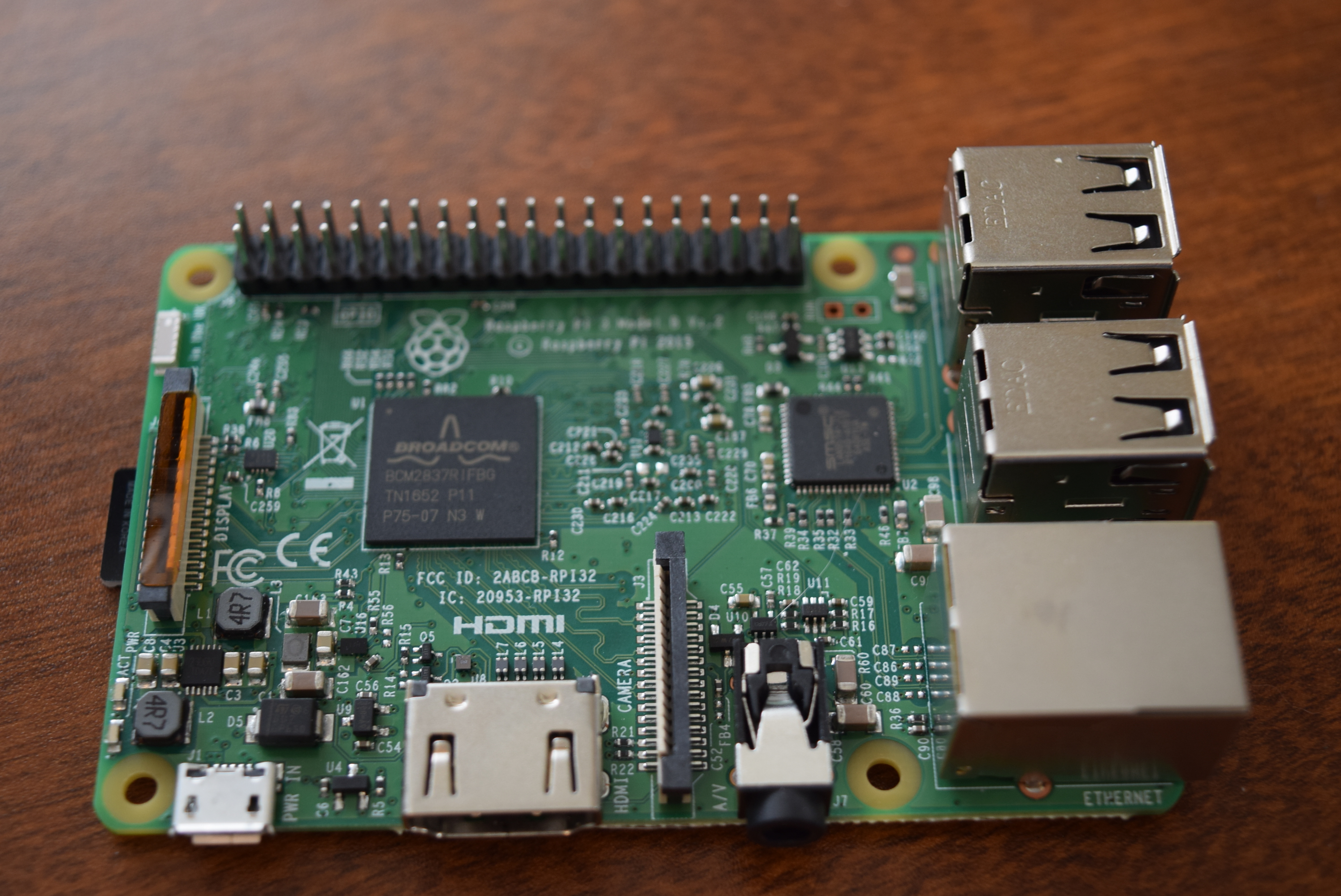
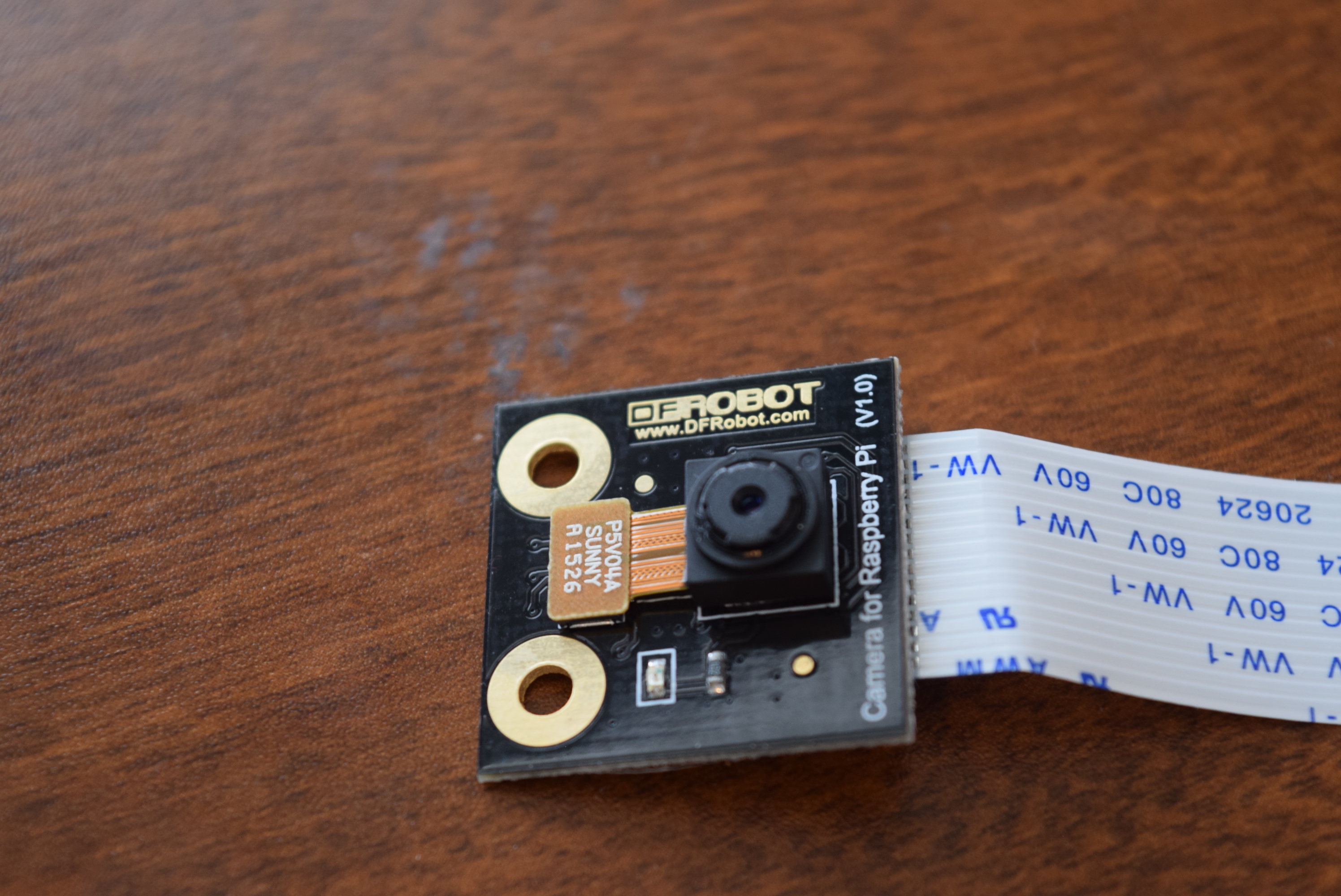
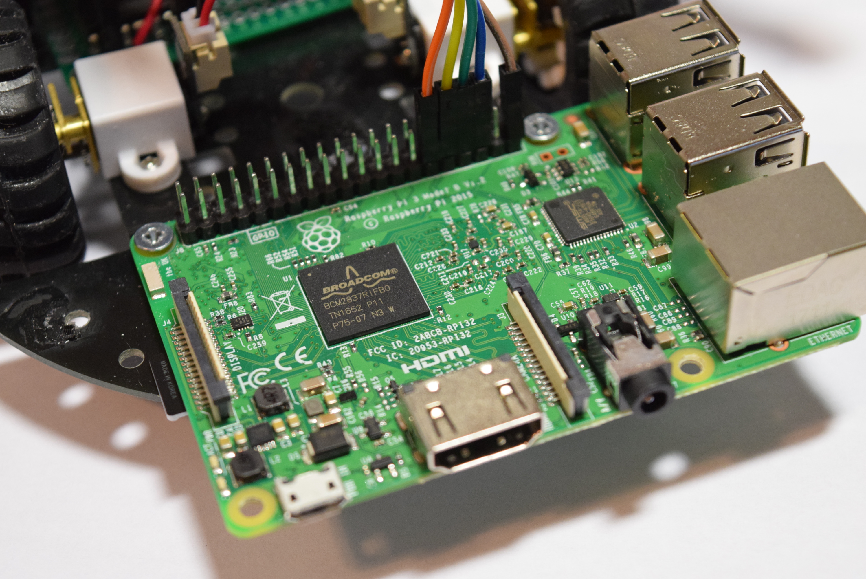
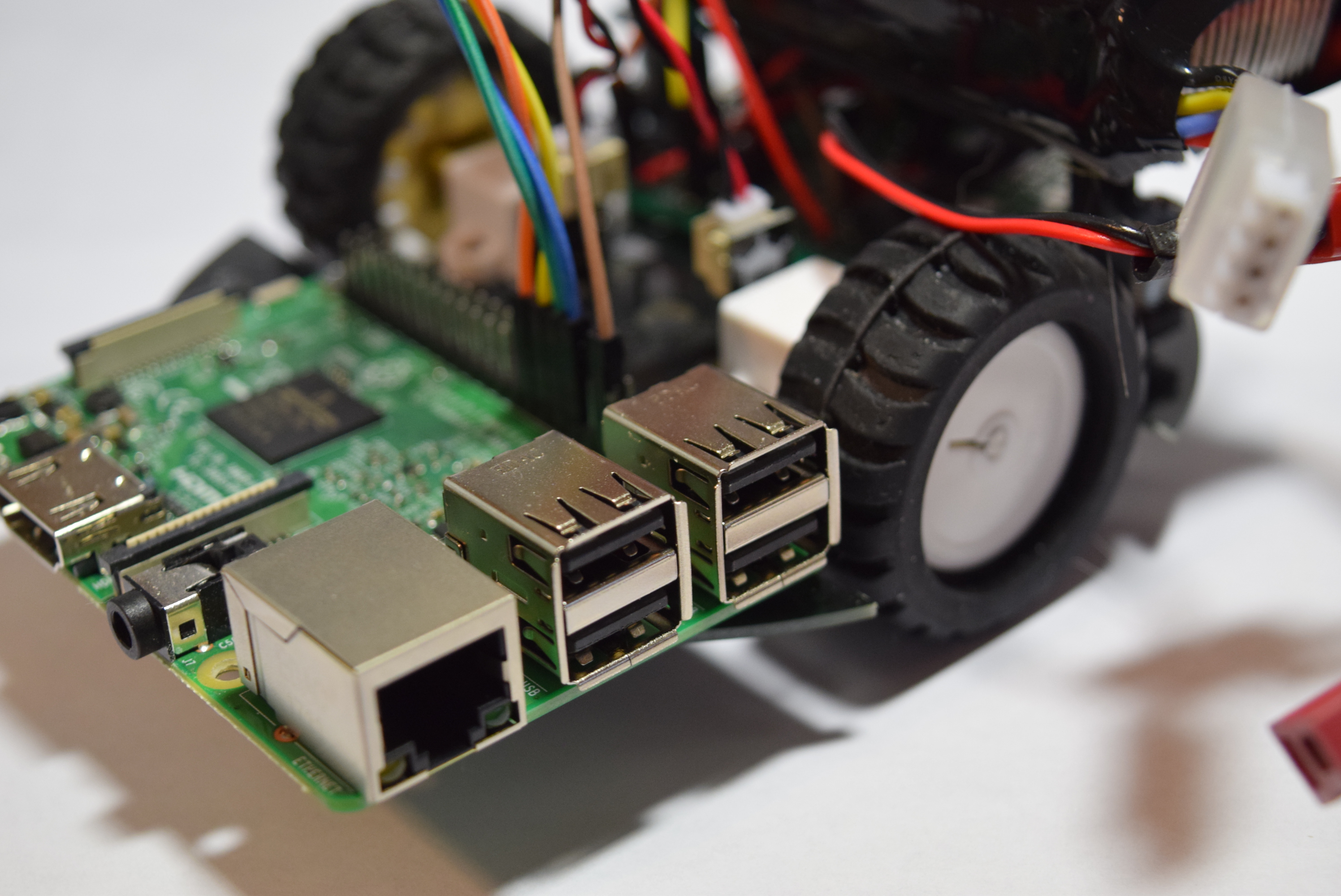
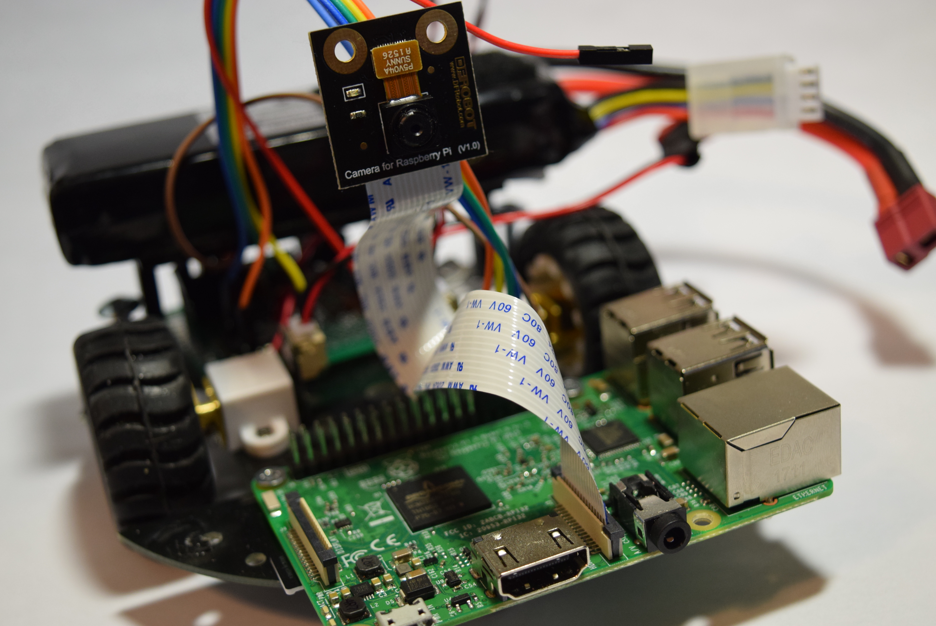
Hardware Setup:1. CSI connector; 90 degrees vertical connector which is next to the HDMI port. When connecting, make sure one side of the contact faces the HDMI interface. 2. Do not forget to tear off the protective film off of the camera lens!3. Also, since the Raspberry Pi is a bare silicon board, take care to not get any electro-static damage!Raspberry Pi Set up – Enabling the Camera1. Open the Command Prompt line 2. 3. 4. 5. 6. Software Setup: 1. RPi firmware and raspi-config have been updated for the camera, please execute apt-get update; Its available online. 2. Select the camera in raspi-config, start the camera driver in the RPi firmware, and then reboot the board. Command to Activate the camera: raspistill -t 20000 -o –
raspistill -t 2000 -o image.jpg < / font> raspistill-t 2000 -o image.jpg -w 640-h 480 raspistill -t 2000 -o image.jpg -q 5 raspistill -t 2000 -o image.jpg - p 100,100,300,200 raspistill -t 2000 -o image.jpg –n raspistill -t 2000 -o image.png - e png raspistill -t 2000 -o image.jpg -x IFD0.Artist = Dreamcolor -x GPS.GPSAltitude = 1235/10 raspistill -t 2000 -o image.jpg -ifx emboss raspistill -t 2000 -o image.jpg -cfx 128: 128 raspistill -t 2000 raspistill -t 600000 -tl 10000 -o image_num_ % d_today.jpg raspistill -t 2000 –o raspistill -t 2000 -o -> my_file.jpg Camera Tech Specs: Sensor size: 3.67 x 2.74 mm (1/4 "format Pixel Count: 2592 x 1944 Pixel Size: 1.4 x 1.4 um Lens: f = 3.6 mm, f / 2.9 Angle of View: 54 x 41 degrees Field of View: 2.0 x 1.33 m at 2 m Full-frame SLR lens equivalent: 35 mm Fixed Focus: 1 m to infinity Video: 1080p at 30 fps with codec H.264 (AVC) Up to 90 fps Video at VGA Board size: 25 x 24 mm (not including flex cable) Because the focal length of the lens is roughly the same as the width of the sensor, it is easy to remember the field of view: at x meters away, you can see about x meters horizontally, assuming 4x3 stills mode. Horizontal field of view in 1080p video mode is 75% of that (75% H x 55% V sensor crop for 1: 1 pixels at 1920x1080).
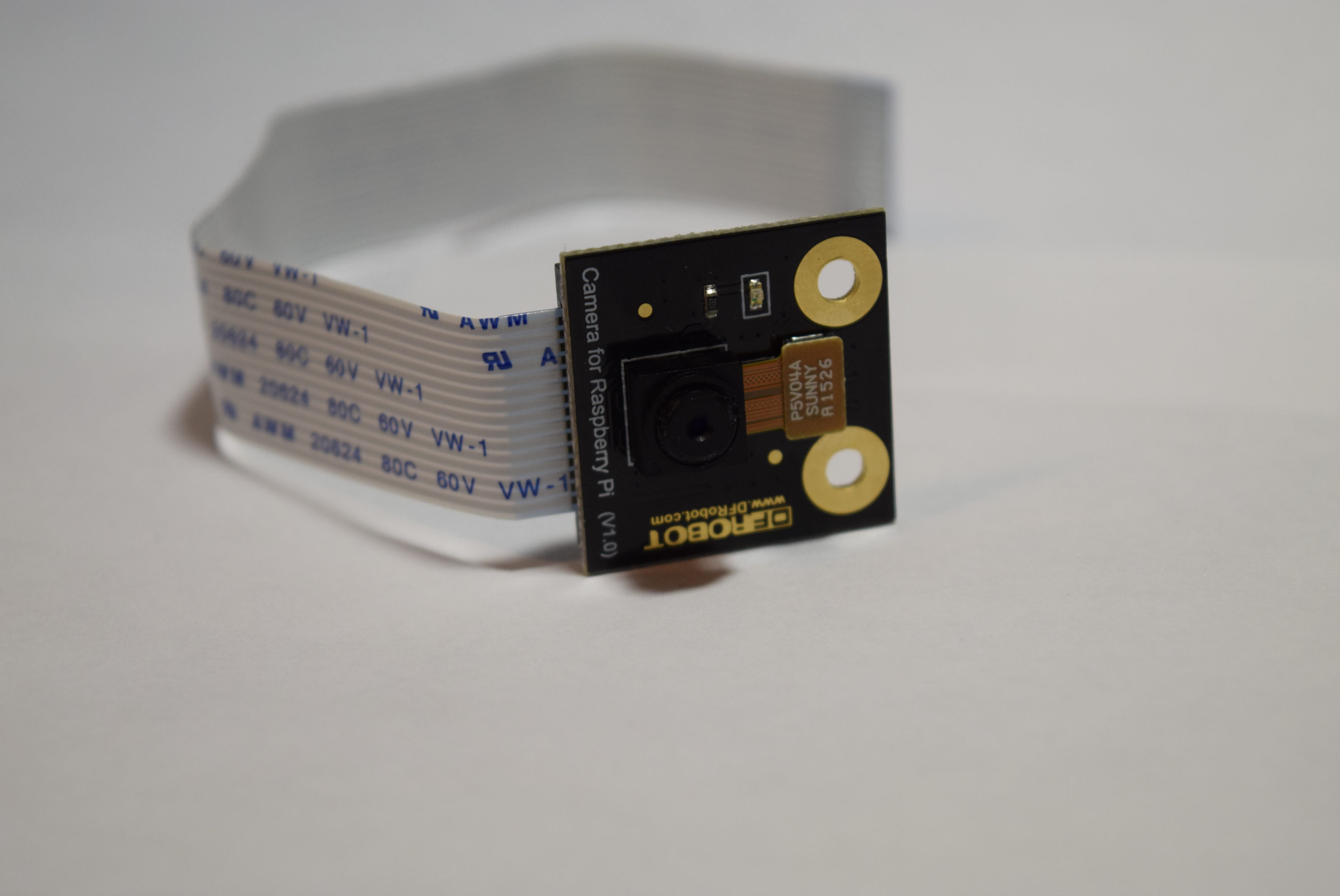
The Raspberry Pi Camera Board features a 5MP (2592×1944 pixels) OmniVision 5647 sensor in a fixed focus module. The module attaches to Raspberry Pi, by way of a 15 Pin Ribbon Cable, to the dedicated 15-pin MIPI Camera Serial Interface (CSI), which was designed especially for interfacing to cameras. The CSI bus is capable of extremely high data rates, and it exclusively carries pixel data to the BCM2835 processor. It is fully Compatible with Both the Model A. Model B Raspberry Pi and B+.
# Take photo and send it to the standard output device for 20s
#two seconds (in milliseconds) delay to take a picture and save it as image in jpg
#Take a custom size photo.
#Reduce the image quality and reduce the file size
#Force the preview window to appear at a position of 100, 100, with a width of 300 and a height of 200 pixels.
#Disable the preview window
#Save the image as a PNG file (lossless compression format, but slower than JPEG). Note that when selecting image encoding, the file extension will be ignored.
#Add some EXIF information to the JPEG file. The command will set the author name tag to Dreamcolor, and the GPS altitude is 123.5 meters.
#Set embossed style image effects
#Set the U and V channels of the YUV image to the specified value (128: 128 is the black and white image)
#Display only two seconds to preview the image without saving the image.
#Get the picture at 10 minutes (10 minutes = 600000 milliseconds), get a copy every 10 seconds, and name it image_number_1_today.jpg, image_number_2_today.jpg and so on…
#Get a photo and send it to a standard output device
#Get a photo and save it as a file
Sensor type: OmniVision OV5647 Color CMOS QSXGA (5-megapixel)
Have you ever wanted to catch that one person who keeps stealing your Halloween candy? Or what about that annoying roommate who won't leave your fridge alone? By using a Raspberry Pi 3, Pi Camera, and PIR sensor, all of that is now possible. Simply put it in a location you want monitored and get emailed with an attached photo of the perpetrator.
Software apps and online services: Python IDE of Choice
Setting Up the Pi
DFRobot reached out to me and sent their Raspberry Pi 3 and Raspberry Pi Camera Module. So after I opened up the boxes I got right to work by setting up the SD card. First I went to the Raspberry Pi Downloads page and downloaded the most recent version of Raspbian. I then extracted the file and put it into a convenient directory. You can't just copy/paste a .img file to an SD card, you have to "burn it" onto the card. You can download a burning utility like Etcher.io to easily transfer the OS image. After the .img file was on my SD card I inserted it into the Raspberry Pi and gave it power. After about 50 seconds I unplugged the cord and removed the SD card. Next I put the SD card back into my PC and went to the "boot" directory. I opened up notepad and saved it as a blank file named "ssh" with NO extension. There was also a file I added called "wpa_supplicant.conf" and put this text into it:
network={
     ssid=<"SSID">
     psk=<"PASSWD">
}
Then I saved and ejected the card and put it back into the Raspberry Pi 3. This should now allow for the usage of SSH and connecting to WiFi.
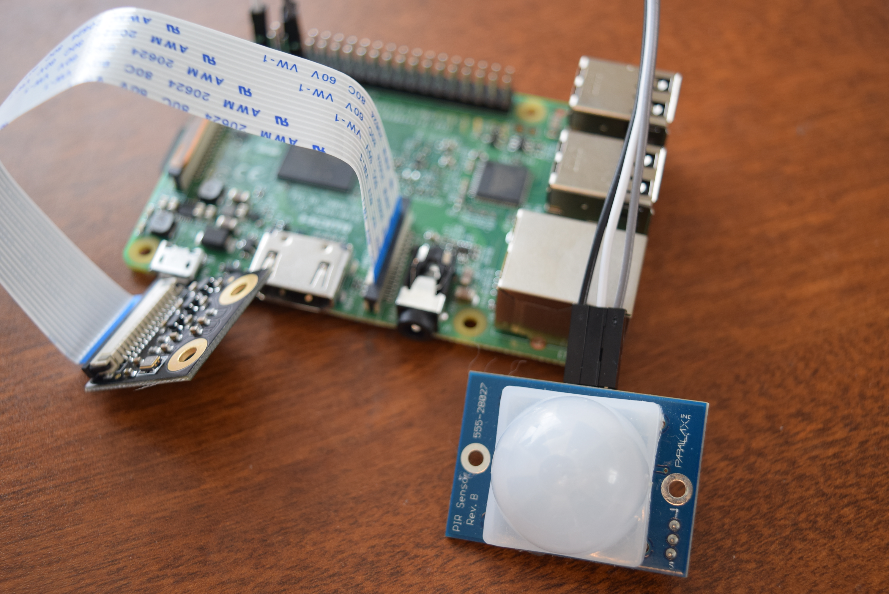
Getting the Camera Ready By default, the camera is disabled on the Pi, so you must open the terminal type sudo raspi-config to bring up the menu. Go to "interfacing options" and then enable the camera. Now just select "Finish" and insert the ribbon cable of the camera module into the correct area of the Pi.
Wiring the PIR Sensor A PIR sensor stands for Passive InfraRed, which basically means it can detect heat, and therefor humans moving in front of it. There are only 3 leads to connect: VCC, GND, and OUTPUT. VCC gets connected to 3.3V, GND to GND of course, and OUTPUT to pin 4 (BCM numbering) on the Pi.
The Code I have attached code to this project page, so all you have to do is copy/paste it, but with one catch. It isn't good practice to store passwords in plain text, let alone a main account password. Therefore, you can go to the Google Accounts page and select security, then app passwords. Add a new one called "Raspberry Pi Email" and copy/paste that 16 character password into the code. This allows you to delete the password after you're done with it, improving security. Also enter the email address for your Google account that you used to setup the app password.
Running It Now simply run the code by typing sudo python <FileName>.py I set my device across from my new stash of Halloween candy to monitor if someone is trying to steal it.
Schematic
CODE
import os
import smtplib
from email.mime.text import MIMEText
from email.mime.image import MIMEImage
from email.mime.multipart import MIMEMultipart
import picamera
import RPi.GPIO as GPIO
from time import sleep

GPIO.setmode(GPIO.BCM)
GPIO.setup(4, GPIO.IN)

subject = "An intruder has been detected"
to = "Your Google email address"
UserName = to
UserPassword = "Your Google Password"

camera = picamera.PiCamera()

def SendMail(ImgFileName):
    img_data = open(ImgFileName, 'rb').read()
    msg = MIMEMultipart()
    msg['Subject'] = subject
    msg['From'] = to
    msg['To'] = to

    text = MIMEText("Here is an attached image of the intruder")
    msg.attach(text)
    image = MIMEImage(img_data, name=os.path.basename(ImgFileName))
    msg.attach(image)

    s = smtplib.SMTP("smtp.gmail.com:587")
    s.ehlo()
    s.starttls()
    s.ehlo()
    s.login(UserName, UserPassword)
    s.sendmail(to, to, msg.as_string())
    print("Sending mail")
    s.quit()

def takePicture(channel):
    camera.capture('image.jpg')
    SendMail('image.jpg')
    os.remove('image.jpg')
    sleep(20)


GPIO.add_event_detect(4, GPIO.RISING, callback=takePicture, bouncetime=500)

while True:
    pass
This raspberry pi 3 project allows you to drive a robot via a webpage and view a livestream. It can be used to spy on pets, make sure nothing is burning in your oven, and even bird watch!
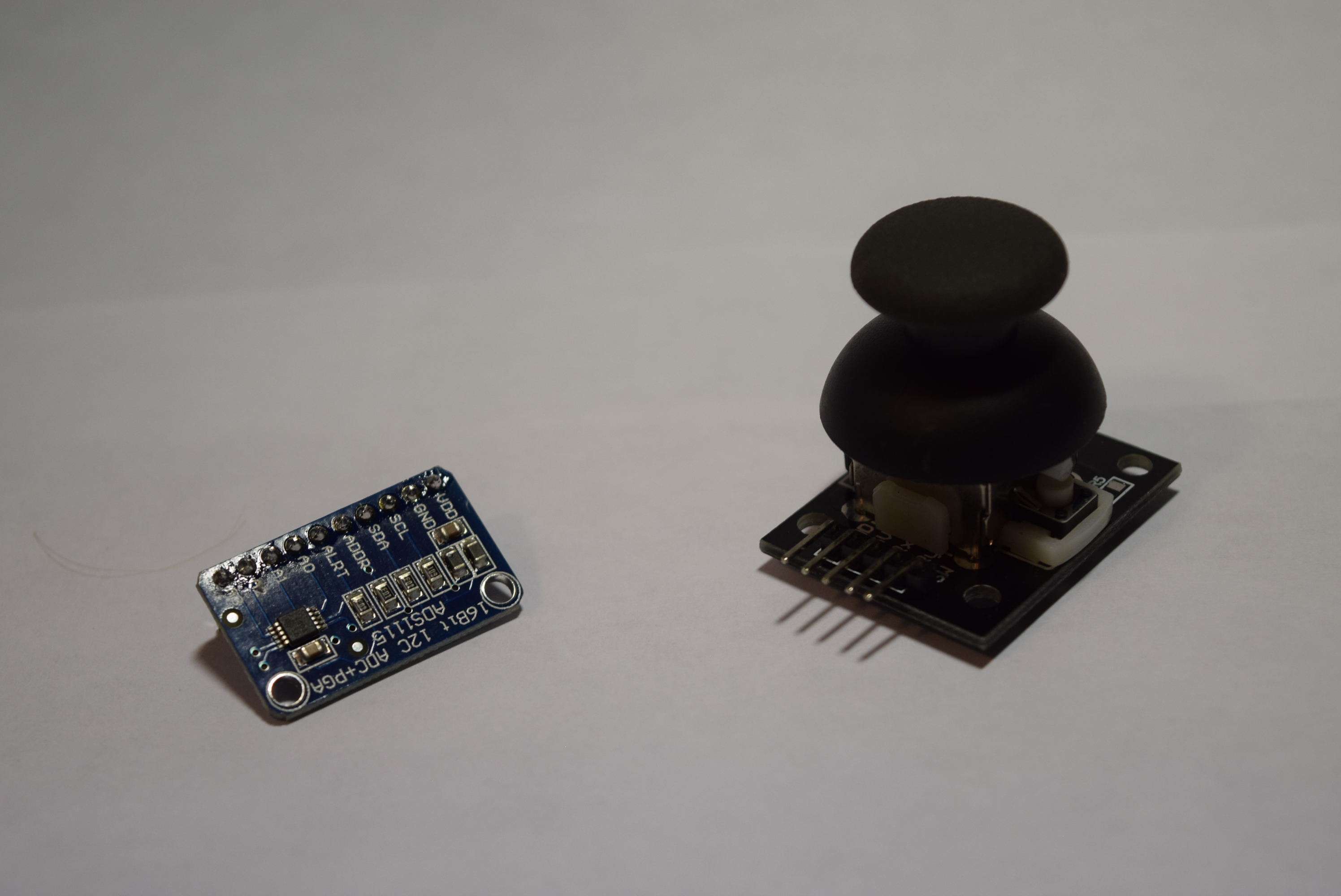
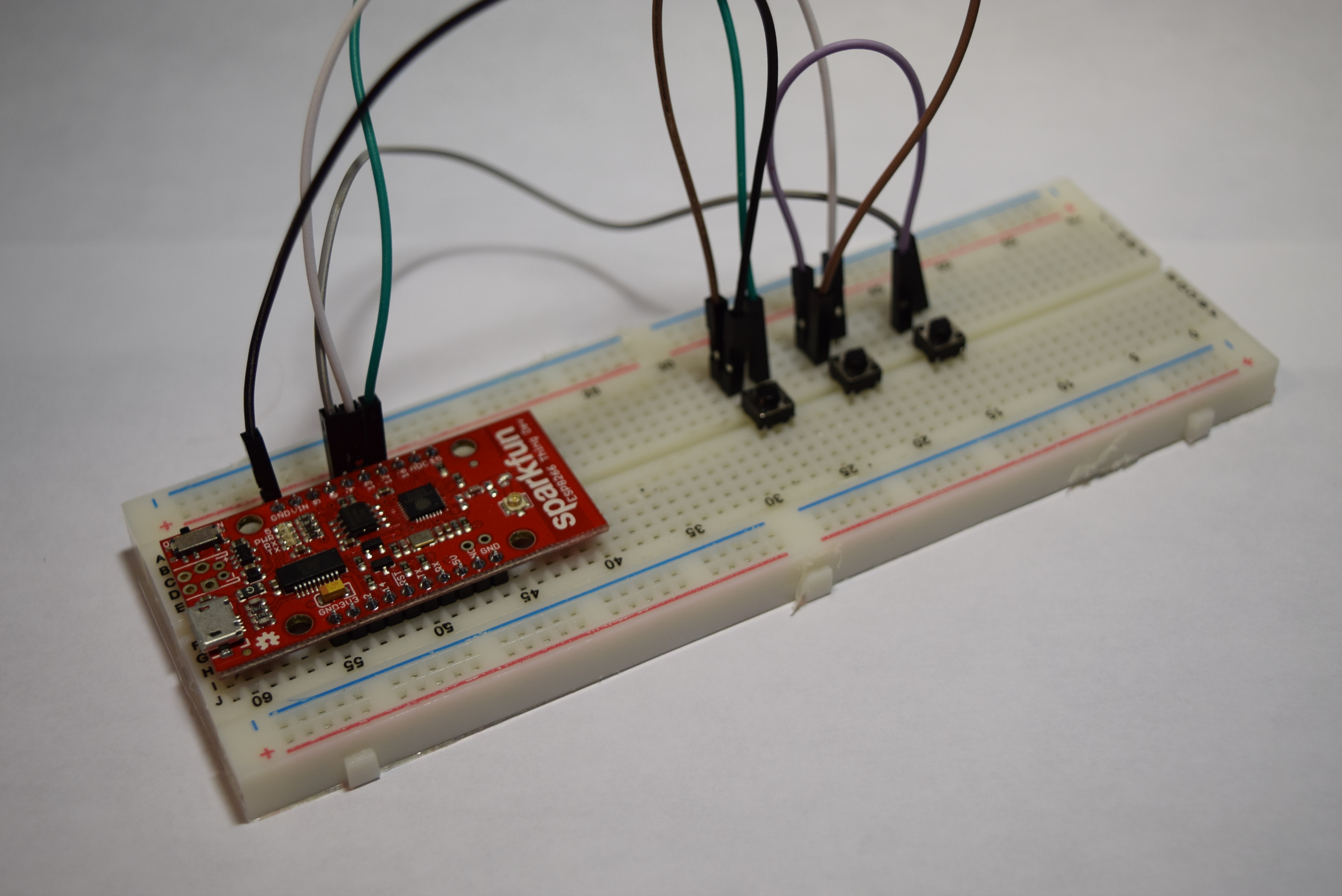
Texas Instruments Dual H-Bridge motor drivers L293D Jumper wires (generic) 5v Regulator 1800 mAh 11.7V LiPo Battery ESP8266 Thing – Dev Board SparkFun Pushbutton switch 12mm DFRobot Raspberry Pi 3 DFRobot Raspberry Pi Camera Module Hand tools and fabrication machines: 3D Printer Then came the part of how to control a Raspberry Pi over WiFi, because Bluetooth has too little range. I decided on using a Flask server running on the Raspberry PI and an ESP8266 ESP12E module to send data to it. The ESP8266 only has one analog input, which means I couldn’t use the joystick directly, as it takes two analog inputs. The best option was the ADS1115, which is an I2C device that reads analog signals at 16 bits of resolution. I simply connected SDA to 4 and SCL to 5, along with VCC and GND. The joystick X axis connects to A0 on the ADS1115, and the Y axis connects to A1. BUT, I accidentally burned out the ADS1115, so I had to resort to the next-best thing: buttons! So now my setup is an ESP8266 Sparkfun Thing Dev Board with 3 buttons- forward, right, and left. Now whenever one is pressed, it sends data to turn the wheels in that direction.
I began by assembling the 2WD MiniQ chassis kit from DFRobot. I slid the wheels onto the motor shafts, then inserted them into brackets and attached them to the chassis. Finally, I added the metal supports.
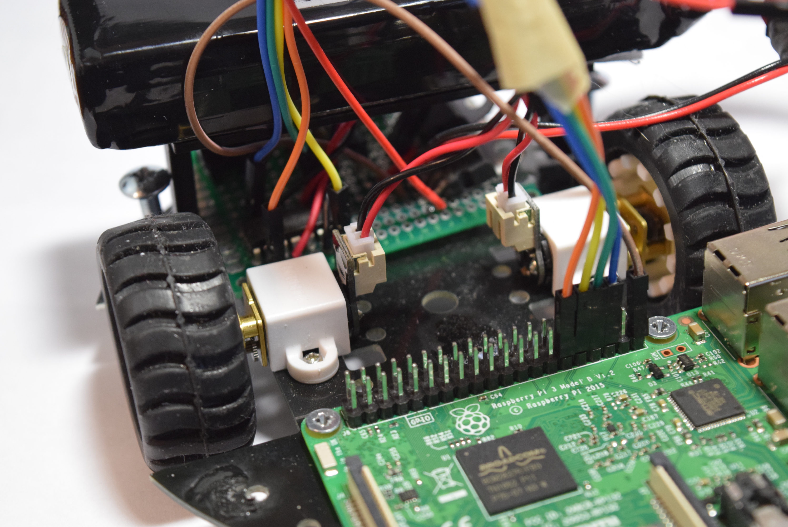
Now it was time to build the main board. The L293d motor driver got soldered in place, along with wires running to the Raspberry Pi’s GPIO pins. Next, I soldered a connector for the battery, as that will provide the main power. After the power source was added, I installed a 5V regulator.
Setting Up the Pi
DFRobot reached out to me and sent their Raspberry Pi 3 and Raspberry Pi Camera Module. So after I opened up the boxes I got right to work by setting up the SD card. First I went to the Raspberry Pi Downloads page and downloaded the most recent version of Raspbian. I then extracted the file and put it into a convenient directory. You can’t just copy/paste a .img file to an SD card, you have to “burn it” onto the card. You can download a burning utility like Etcher.io to easily transfer the OS image. After the .img file was on my SD card I inserted it into the Raspberry Pi and gave it power. After about 50 seconds I unplugged the cord and removed the SD card. Next I put the SD card back into my PC and went to the “boot” directory. I opened up notepad and saved it as a blank file named “ssh” with NO extension. There was also a file I added called “wpa_supplicant.conf” and put this text into it:
network={ ssid=<“SSID”> psk=<“PASSWD”> }
Then I saved and ejected the card and put it back into the Raspberry Pi 3. This should now allow for the usage of SSH and connecting to WiFi.
Getting the Camera Ready
By default, the camera is disabled on the Pi, so you must open the terminal type sudo raspi-config to bring up the menu. Go to “interfacing options” and then enable the camera. Now just select “Finish” and insert the ribbon cable of the camera module into the correct area of the Pi.
Installing Software
There are several different softwares that can stream video, such as vlc and motion, but I decided to use the mjpeg-streamer due to its low latency and easy installation. According to the instructions on the site, do a git clone https://github.com/jacksonliam/mjpg-streamer.git into a folder, then type sudo apt-get install cmake libjpeg8-dev to install the needed libraries. Change your directory into the folder you downloaded and then type make followed by sudo make install to compile the software. Finally enter export LD_LIBRARY_PATH=. and to run it type ./mjpg_streamer -o “output_http.so -w ./www” -i “input_raspicam.so” You can access the stream by heading to http://<The Pi’s Local IP>:8080/stream.html to view the stream.
Controller
The Code for the Robot
I made a previous project that utilized the Pi’s GPIO PWM library to control motors via json, so I just re-purposed the code to accept data via a Flask app instead. Flask is a Python library that essentially turn your Pi into a webserver capable of sending and receiving data. By using PWM, the motors can be controlled with greater precision compared to tank drive. This also means the robot can go at variable speeds rather than a fixed one. My flask app is configured to change the PWM of the motors once it receives data from a GET request via http from the ESP12e. It also uses the subprocess.Popen library to run the webstreaming script in the background. I have attached code to the project page, so all that is necessary is a download.
Controller Code
The code was pretty simple, just take readings from the 3 pins, run them through some if statements to determine wheel direction, and finally send those values to the Raspberry Pi. The ESP8266 board addition for the Arduino IDE comes with the HTTPClient library, which handles headers and sending data. The Flask server needs to receive data via a POST call, so the code starts a connection with the Raspberry Pi webserver, then adds a header to the data denoting that it’s JSON encoded, and finally it sends the data in the form of a JSON object. I added a 40 ms delay to prevent the Raspberry Pi from becoming overloaded with data.
Running the Raspberry SPy
All that is required is typing sudo python <raspberryspycode>.py ! You should see the camera light up, and by going to the web address of the pi with the port 8080 the stream should be visible. Now you can use the controller anywhere in the house and have a live feed as well.
SCHEMATICS
CODE
#include <Arduino.h>
#include <ESP8266WiFi.h>
#include <ESP8266WiFiMulti.h>

#include <ESP8266HTTPClient.h>

ESP8266WiFiMulti WiFiMulti;

#define SSID "SSID"
#define PSSWD "PASSWORD"

int pins[3] = {12,13,4};

void setup() {
  // put your setup code here, to run once:
  Serial.begin(9600);
  for(int i=0; i<3;i++){
    pinMode(pins[i], INPUT_PULLUP);
  }
  WiFiMulti.addAP(SSID, PSSWD);
}

void loop() {
  // put your main code here, to run repeatedly:
  int motor1, motor2;
  if(digitalRead(pins[0])==0){ //Turn left
    Serial.println("left");
    motor1 = 50;
    motor2 = 50;
  }
  else if(digitalRead(pins[1])==0){ //Go forward
    Serial.println("forward");
    motor1 = 50;
    motor2 = -50;
  }
  else if(digitalRead(pins[2])==0){ //Turn right
    Serial.println("right");
    motor1 = -50;
    motor2 = -50;
  }
  else{
    motor1 = 0;
    motor2 = 0;
  }

  if(WiFiMulti.run() == WL_CONNECTED){
    HTTPClient http;
    http.begin("http://<RaspberryPiIP:5000/control/");
    http.addHeader("Content-Type", "application/json");
    int httpCode = http.POST("{\"motor1\":"+String(motor1)+", \"motor2\":"+String(motor2)+"}");
    String payload = http.getString();
    Serial.print('\t');
    Serial.println(httpCode);
    Serial.println(payload);
  }
  delay(40);
}